
TM 5-2420-231-23-2
0210
DISASSEMBLY CONTINUED
CAUTION
U-joint will bottom out on yoke of driveshaft before it is loose in driveshaft yoke. Stop using
ball joint service kit at this point. Failure to follow this caution will result in damage to the
machine.
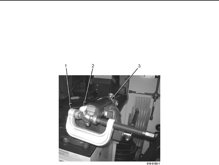
2. Using ball joint service kit (Figure 4, Item 1), remove U-joint (Figure 4, Item 2) from front axle drive shaft
(Figure 4, Item 3).
Figure 4. U-Joint.
0210
END OF TASK
CLEANING AND INSPECTION
0210
Clean and inspect all parts IAW Mechanical General Maintenance Instructions (WP 0369).
END OF TASK
ASSEMBLY
0210
NOTE
The procedure for front axle drive shaft U-joint removal and replacement is identical for
forward and rearward front axle drive shaft U-joints. Forward front axle drive shaft U-joint
is shown in this procedure.
1. Using ball joint service kit (Figure 4, Item 1), install U-joint (Figure 4, Item 2) in front axle drive shaft
(Figure 4, Item 3).