TM 5-2420-231-23-2
0210
REMOVAL CONTINUED
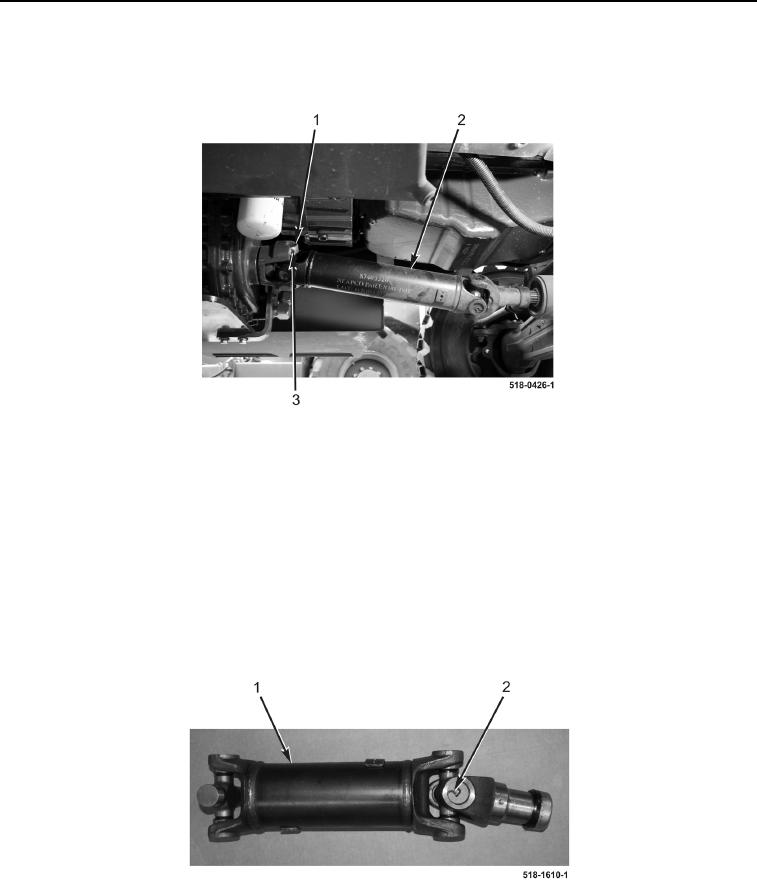
2. Remove four bolts (Figure 2, Item 3), two clamps (Figure 2, Item 1), and front axle drive shaft (Figure 2, Item 2)
from machine.
Figure 2. Drive Shaft.
0210
END OF TASK
DISASSEMBLY
0210
NOTE
The procedure for front axle drive shaft U-joint removal and replacement is identical for
forward and rearward front axle drive shaft U-joints. Forward front axle drive shaft U-joint
is shown in this procedure.
1. Remove four retaining rings (Figure 3, Item 2) from front axle drive shaft (Figure 3, Item 1).
Figure 3. Retaining Rings.
0210

