
TM 5-2420-231-23-2
0210
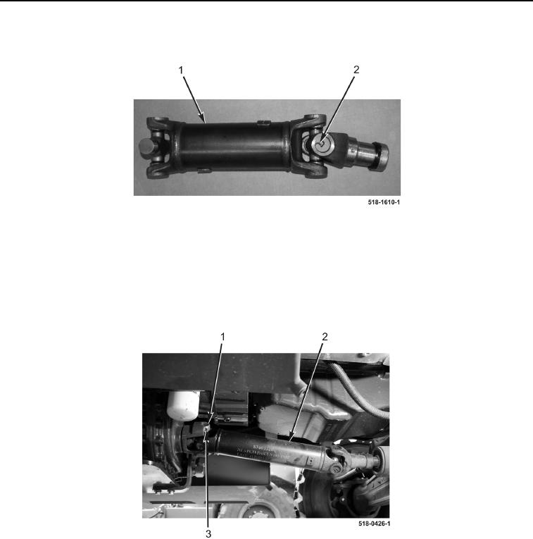
ASSEMBLY CONTINUED
2. Install four retaining rings (Figure 5, Item 2) on front axle drive shaft (Figure 5, Item 1).
Figure 5. Retaining Rings.
0210
END OF TASK
INSTALLATION
0210
1. Install front axle drive shaft (Figure 6, Item 2), two clamps (Figure 6, Item 1), and four bolts (Figure 6, Item 3)
on machine.
Figure 6. Drive Shaft.
0210