
TM 5-2420-231-23-2
0219
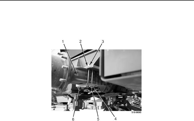
INSTALLATION CONTINUED
5. Install two mounts (Figure 4, Item 6), eight washers (Figure 4, Item 4), bolts (Figure 4, Item 5), washers
(Figure 4, Item 2), and nuts (Figure 4, Item 3) on rear drive axle housing (Figure 4, Item 1). Torque bolts to
380 lb-ft (515 Nm).
6. Remove suitable lifting device from rear drive axle housing.
Figure 4. Rear Drive Axle Installation.
0219
7. Install two park brake cables (Figure 5, Item 3), pins (Figure 5, Item 4), and new cotter pins (Figure 5, Item 5)
on rear drive axle housing (Figure 5, Item 9).
8. Connect differential lock hose (Figure 5, Item 6) to rear drive axle housing (Figure 5, Item 9).
9. Connect two wiring harness connectors (Figure 5, Item 2) to park brake switch (Figure 5, Item 1).
10. Connect wiring harness connector (Figure 5, Item 7) to oil sending unit (Figure 5, Item 8).