
TM 5-2420-231-23-2
0222
DISASSEMBLY
0222
NOTE
The following procedure shows one U-joint removal. Use the same procedure for the other
rear drive axle drive shaft U-joint.
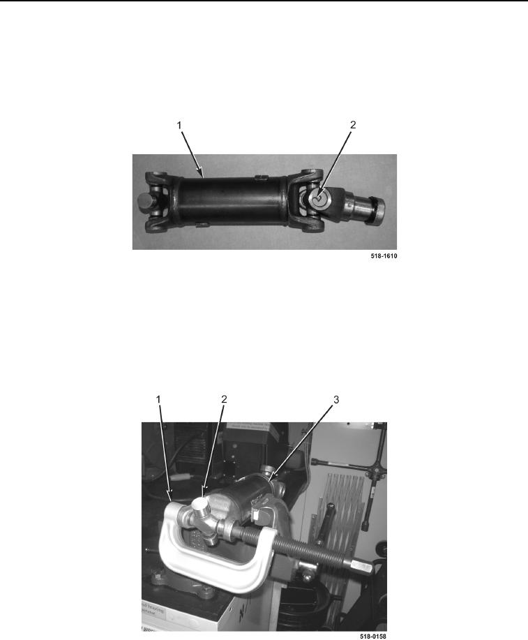
1. Remove four retaining rings (Figure 2, Item 2) from rear drive axle drive shaft (Figure 2, Item 1).
Figure 2. Retaining Rings.
0222
CAUTION
U-joint will bottom out on yoke of drive shaft before it is loose in drive shaft yoke. Stop
using ball joint service kit at this point. Failure to follow this caution will result in damage to
the machine.
2. Using ball joint service kit (Figure 3, Item 1), remove U-joint (Figure 3, Item 2) from rear drive axle drive shaft
(Figure 3, Item 3).
Figure 3. U-Joint.
0222
END OF TASK