
TM 5-2420-231-23-2
0226
REMOVAL CONTINUED
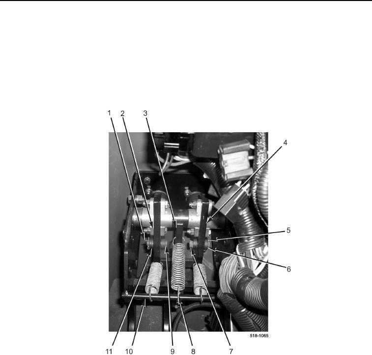
5. Disconnect spring (Figure 4, Item 8) from rod (Figure 4, Item 10).
6. Allow brake lamp arm (Figure 4, Item 3) to rotate away from rod (Figure 4, Item 10).
7. Remove cotter pin (Figure 4, Item 1) from pin (Figure 4, Item 9). Discard cotter pin.
8. Remove pin (Figure 4, Item 9) from brake clevis (Figure 4, Item 11) and brake pedal (Figure 4, Item 2).
9. Remove cotter pin (Figure 4, Item 5) from pin (Figure 4, Item 7). Discard cotter pin.
10. Remove pin (Figure 4, Item 7) from brake clevis (Figure 4, Item 6) and brake pedal (Figure 4, Item 4).
Figure 4. Brake Pedal Pins.
0226