
TM 5-2420-231-23-2
0226
DISASSEMBLY CONTINUED
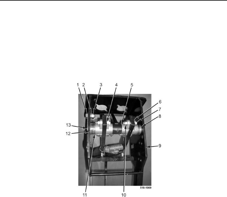
5. Loosen four locknuts (Figure 8, Item 10) and bolts (Figure 8, Item 7).
6. Remove nut (Figure 8, Item 3), lockwasher (Figure 8, Item 2), and bolt (Figure 8, Item 1) from brake pedal
bracket (Figure 8, Item 9). Discard lockwasher.
NOTE
Note location and quantity of washers to aid in installation.
7. Remove brake pedal rod (Figure 8, Item 13), spacer (Figure 8, Item 8), right brake pedal (Figure 8, Item 6),
brake lamp arm (Figure 8, Item 5), left brake pedal (Figure 8, Item 4), washers (Figure 8, Item 11), and spacer
(Figure 8, Item 12) from brake pedal bracket (Figure 8, Item 9).
Figure 8. Brake Pedal Rod.
0226