
TM 5-2420-231-23-2
0226
REMOVAL CONTINUED
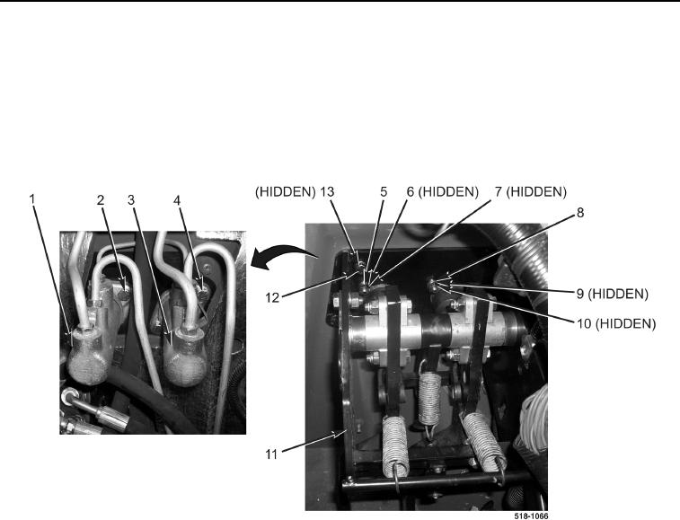
11. Remove two nuts (Figure 5, Item 5), lockwashers (Figure 5, Item 6), washers (Figure 5, Item 7), and bolts
(Figure 5, Item 4) from left master cylinder (Figure 5, Item 3). Discard lockwashers.
12. Remove two nuts (Figure 5, Item 8), lockwashers (Figure 5, Item 9), washers (Figure 5, Item 10), and bolts
(Figure 5, Item 2) from right master cylinder (Figure 5, Item 1). Discard lockwashers.
13. Remove four bolts (Figure 5, Item 12), lockwashers (Figure 5, Item 13), and brake pedal bracket
(Figure 5, Item 11) from machine. Discard lockwashers.
Figure 5. Brake Pedal Bracket Bolts.
0226
END OF TASK