
TM 5-2420-231-23-2
0226
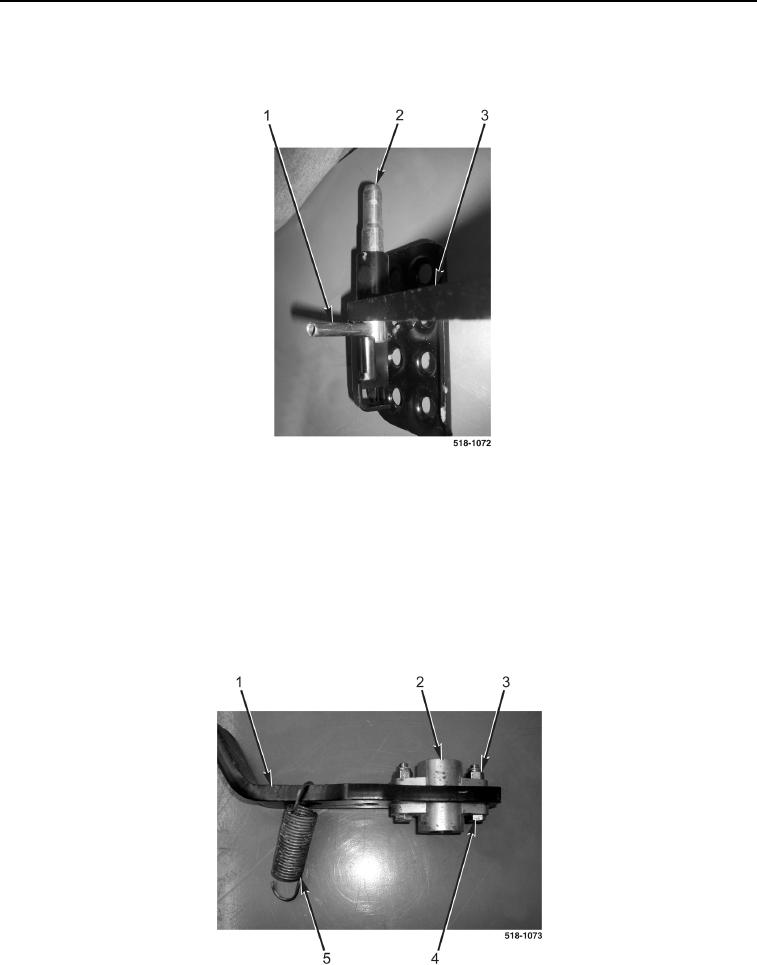
DISASSEMBLY CONTINUED
12. Remove spring pin (Figure 10, Item 1) from brake pedal lock (Figure 10, Item 2).
13. Remove brake pedal lock (Figure 10, Item 2) from left brake pedal (Figure 10, Item 3).
Figure 10. Brake Pedal Lock.
0226
NOTE
The procedure for brake pedal disassembly and assembly is identical for left-hand and
right-hand brake pedals. Left-hand brake pedal is shown in this procedure.
14. Disconnect return spring (Figure 11, Item 5) from brake pedal (Figure 11, Item 1).
15. Remove two locknuts (Figure 11, Item 3), bolts (Figure 11, Item 4) and brake pedal bushing (Figure 11, Item 2)
from brake pedal (Figure 11, Item 1). Discard locknuts.
16. Repeat steps 13 and 14 on right brake pedal.
Figure 11. Brake Pedal.
0226