
TM 5-2420-231-23-2
0226
DISASSEMBLY CONTINUED
NOTE
Note position of brake light switch stop and jamnut to aid in installation.
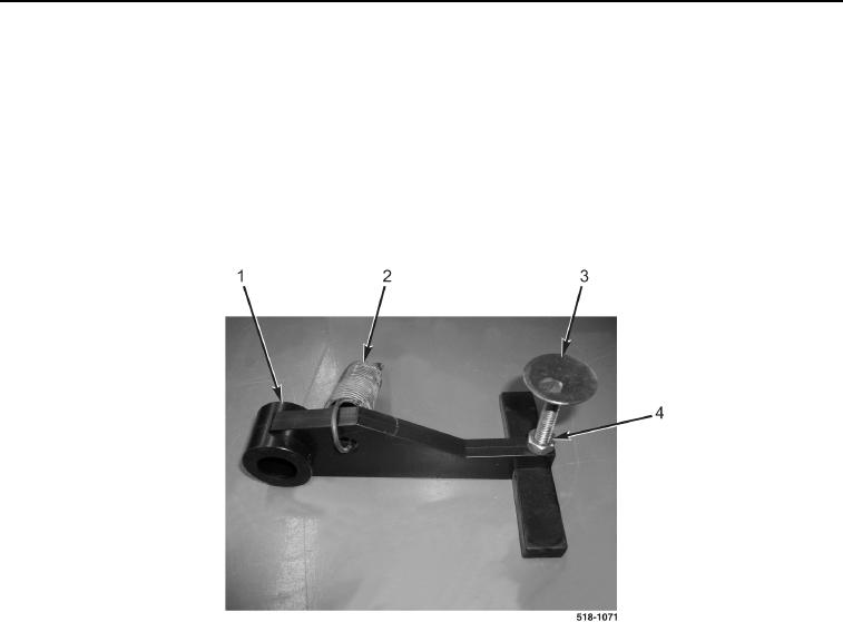
17. Disconnect return spring (Figure 12, Item 2) from brake lamp arm (Figure 12, Item 1).
18. Loosen jamnut (Figure 12, Item 4) on brake light switch stop (Figure 12, Item 3).
19. Remove brake light switch stop (Figure 12, Item 3) from brake lamp arm (Figure 12, Item 1).
20. Remove jamnut (Figure 12, Item 4) from brake light switch stop (Figure 12, Item 3).
Figure 12. Brake Lamp Arm.
0226
END OF TASK
CLEANING AND INSPECTION
0226
1. Clean and inspect all parts IAW Mechanical General Maintenance Instructions (WP 0369).
2. Clean and inspect all parts IAW Electrical General Maintenance Instructions (WP 0370).
END OF TASK
ASSEMBLY
0226
NOTE
Install parking brake light switch stop and jamnut as noted during removal.
1. Install jamnut (Figure 12, Item 4) on brake light switch stop (Figure 12, Item 3).
2. Install brake light switch stop (Figure 12, Item 3) on brake lamp arm (Figure 12, Item 1) as noted during
removal.
3. Tighten jamnut (Figure 12, Item 4) on brake light switch stop (Figure 12, Item 3).
4. Connect return spring (Figure 12, Item 2) to brake lamp arm (Figure 12, Item 1).