
TM 5-2420-231-23-2
0226
ADJUSTMENT
0226
1. Remove front floor mat (WP 0305).
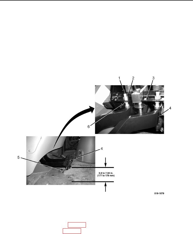
2. Brake pedals (Figure 24, Item 4) should be 6.9 to 7.04 in. (177 to 179 mm) above floor with mat removed.
3. To adjust brake pedal height:
a. Disengage brake pedal lock (Figure 24, Item 5) for brake pedals (Figure 24, Item 4).
b. Loosen locknuts (Figure 24, Items 2 and 6) on stop bolt (Figure 24, Item 1).
c.
Adjust stop bolt (Figure 24, Item 1) and locknuts (Figure 24, Items 2 and 6) until brake pedal is 6.9 to
7.04 in. (177 to 179 mm) above floor with mat removed.
d. Tighten locknuts (Figure 24, Items 2 and 6) and stop bolt (Figure 24, Item 1) to brake pedal bracket
(Figure 24, Item 3).
4. Install front floor mat (WP 0305).
Figure 24. Brake Pedal Height Adjustment.
0226
END OF TASK
FOLLOW-ON TASKS
0226
1. Install instrument panel front cover (WP 0174).
2. Install air cleaner barrier curtain (WP 0099).
END OF TASK
END OF WORK PACKAGE