
TM 5-2420-231-23-2
0227
CLEANING AND INSPECTION
0227
Clean and inspect all parts IAW Mechanical General Maintenance Instructions (WP 0369).
END OF TASK
INSTALLATION
0227
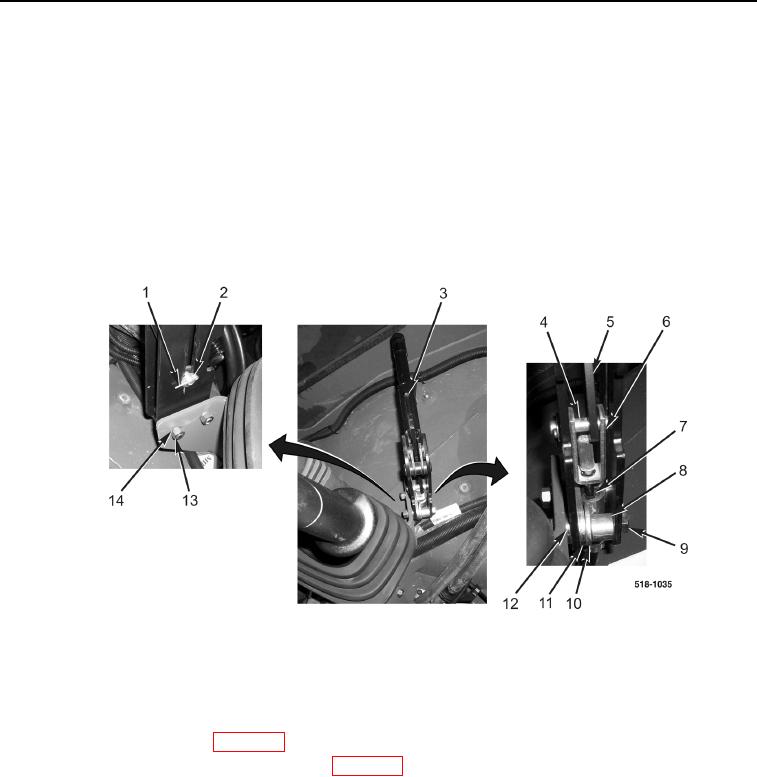
1. Install parking brake lever assembly (Figure 2, Item 3), two bolts (Figure 2, Item 9), spacers (Figure 2, Item 8),
retaining plate (Figure 2, Item 10), spacer plate (Figure 2, Item 11), two washers (Figure 2, Item 12), new
lockwashers (Figure 2, Item 14), and nuts (Figure 2, Item 13) on brake cable (Figure 2, Item 7) and machine.
2. Install retaining pin (Figure 2, Item 4), washer (Figure 2, Item 2), and new cotter pin (Figure 2, Item 1) on brake
cable clevis (Figure 2, Item 6) and parking brake handle (Figure 2, Item 5).
Figure 2. Parking Brake Lever Assembly.
0227
END OF TASK
FOLLOW-ON TASKS
0227
1. Adjust parking brake cable (WP 0228).
2. Install instrument panel right-side front cover (WP 0176).
END OF TASK
END OF WORK PACKAGE