
TM 5-2420-231-23-2
0226
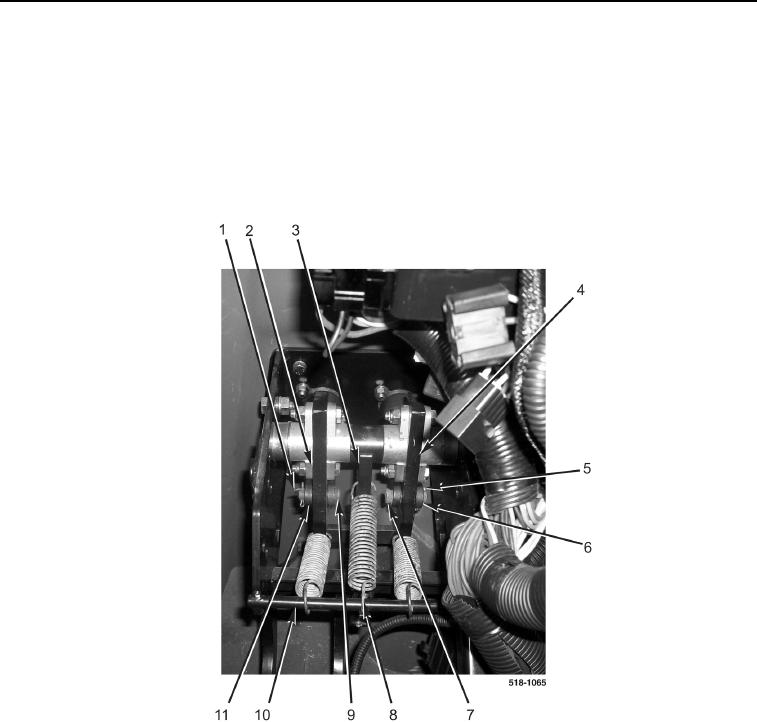
INSTALLATION CONTINUED
4. Install pin (Figure 20, Item 7) on brake clevis (Figure 20, Item 6) and brake pedal (Figure 20, Item 4).
5. Install new cotter pin (Figure 20, Item 5) on pin (Figure 20, Item 7).
6. Install pin (Figure 20, Item 9) on brake clevis (Figure 20, Item 11) and brake pedal (Figure 20, Item 2).
7. Install new cotter pin (Figure 20, Item 1) on pin (Figure 20, Item 9).
8. Rotate brake lamp arm (Figure 20, Item 3) toward rod (Figure 20, Item 10).
9. Connect spring (Figure 20, Item 8) to rod (Figure 20, Item 10).
Figure 20. Brake Pedal Pins.
0226