
TM 5-2420-231-23-2
0226
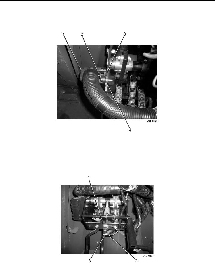
INSTALLATION CONTINUED
12. Install fuse box (Figure 22, Item 1), bolt (Figure 22, Item 2), and new locknut (Figure 22, Item 4) on brake pedal
bracket (Figure 22, Item 3).
Figure 22. Fuse Box.
0226
NOTE
Install wires as tagged and marked during removal.
13. Install two wires (Figure 23, Item 2)and screws (Figure 23, Item 3) on brake light switch (Figure 23, Item 1).
Figure 23. Brake Light Wires.
0226
END OF TASK