
2
TM 5-2420-231-23-2
FIELD MAINTENANCE
-
PARKING BRAKE LEVER ASSEMBLY REPLACEMENT
0
227
Removal, Cleaning and Inspection, Installation
INITIAL SETUP
Tools and Special Tools
Equipment Conditions
Tool Kit, General Mechanic's
Wheels blocked (TM 5-2420-231-10)
0
0
(WP 0376, Item 117)
Instrument panel right-side front cover
0
removed (WP 0176)
Materials/Parts
Estimated Time to Complete
Cotter Pin
0
Lockwasher (2)
2.0 hr
0
0
References
0
WP 0369
0
WP 0374 (Group Number 0605)
0
REMOVAL
0227
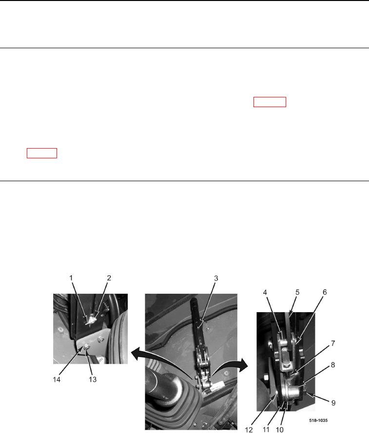
1. Remove cotter pin (Figure 1, Item 1), washer (Figure 1, Item 2), and retaining pin (Figure 1, Item 4) from brake
cable clevis (Figure 1, Item 6) and parking brake handle (Figure 1, Item 5). Discard cotter pin.
2. Remove two nuts (Figure 1, Item 13), lockwashers, (Figure 1, Item 14), washers (Figure 1, Item 12), spacer
plate (Figure 1, Item 11), retaining plate (Figure 1, Item 10), two spacers (Figure 1, Item 8), bolts (Figure 1,
Item 9), and parking brake lever assembly (Figure 1, Item 3) from brake cable (Figure 1, Item 7) and machine.
Discard lockwashers.
Figure 1. Parking Brake Lever Assembly.
0227
END OF TASK