
TM 5-2420-231-23-3
0249
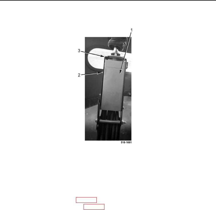
INSTALLATION CONTINUED
14. Install cover (Figure 10, Item 1) and four bolts (Figure 10, Item 2) on control tower (Figure 10, Item 3).
Figure 10. Cover.
0249
15. Repeat steps 9 through 14 for left pilot controls joystick hydraulic hoses.
16. Install cap on hydraulic oil tank (TM 5-2420-231-10).
END OF TASK
FOLLOW-ON TASKS
0249
1. Install backhoe control tower boots (WP 0287).
2. Install rear seat suspension and mount (WP 0310).
3. Check hydraulic oil level and fill as necessary (TM 5-2420-231-10).
END OF TASK
END OF WORK PACKAGE
0249-9/(10 blank)