
TM 5-2420-231-23-3
0249
REMOVAL CONTINUED
NOTE
Note location and quantity of tiedown straps to aid in installation.
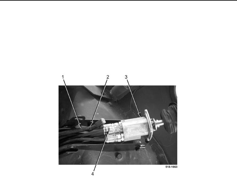
5. Remove tiedown strap (Figure 3, Item 2) from wiring harness (Figure 3, Item 1). Discard tiedown strap.
6. Disconnect six hydraulic hoses (Figure 3, Item 4) from control unit (Figure 3, Item 3) and position control unit
aside.
7. Repeat steps 2 through 6 for left pilot controls hydraulic hoses.
Figure 3. Pilot Control Unit.
0249
8. Disconnect two right pilot control joystick hydraulic hoses (Figure 4, Item 2) from backhoe control valve
(Figure 4, Item 1).
9. Remove two right pilot control joystick hydraulic hoses (Figure 4, Item 2) from machine.
10. Disconnect two left pilot control joystick hydraulic hoses (Figure 4, Item 3) from backhoe control valve
(Figure 4, Item 1).
11. Remove two left pilot control joystick hydraulic hoses (Figure 4, Item 3) from machine.