
2
TM 5-2420-231-23-3
FIELD MAINTENANCE
-
RETURN-TO-DIG SOLENOID REPLACEMENT
026
2
Removal, Cleaning and Inspection, Installation
INITIAL SETUP
Tools and Special Tools
References - Continued
Tool Kit, General Mechanic's
WP 0374 (Group Number 0726)
0
0
(WP 0376, Item 117)
Equipment Conditions
Materials/Parts
Machine parked (TM 5-2420-231-10)
0
Rag, Wiping (WP 0375, Item 25)
Batteries disconnected (WP 0157)
0
0
References
Estimated Time to Complete
0.5 hr
0
0
0
REMOVAL
0262
NOTE
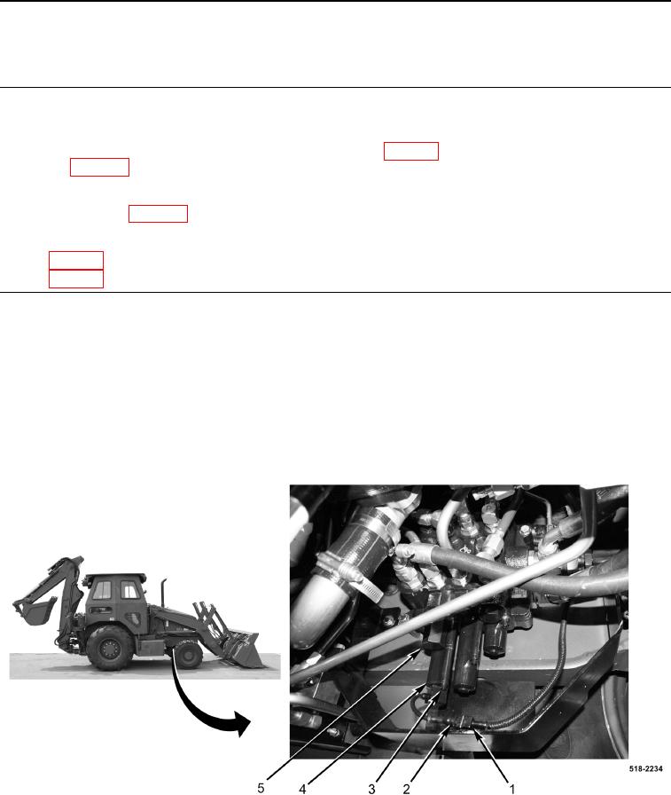
Note position and orientation of return-to-dig solenoid to aid in installation.
1. Disconnect harness connector (Figure 1, Item 1) from return-to-dig solenoid harness (Figure 1, Item 2).
2. Remove two bolts (Figure 1, Item 3) and return-to-dig solenoid (Figure 1, Item 4) from return-to-dig valve
(Figure 1, Item 5).
Figure 1. Loader Control Valve.
0262
END OF TASK