
TM 5-2420-231-23-3
0271
REMOVAL CONTINUED
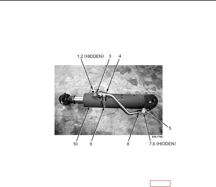
11. Remove clamp (Figure 5, Item 9) and resilient mount (Figure 5, Item 4) from clam cylinder (Figure 5, Item 10).
12. Disconnect tube (Figure 5, Item 8) from fitting (Figure 5, Item 7).
13. Loosen two nuts (Figure 5, Items 3 and 5) and remove fittings (Figure 5, Items 1 and 7) and O-rings (Figure 5,
Items 2 and 6) from clam cylinder (Figure 5, Item 10). Discard O-rings.
14. Repeat steps 6 through 13 for right-hand clam cylinder.
Figure 5. Cylinder.
0271
END OF TASK
CLEANING AND INSPECTION
0271
Clean and inspect all parts IAW Mechanical General Maintenance Instructions (WP 0369).
END OF TASK