
TM 5-2420-231-23-3
0271
INSTALLATION
0271
WARNING
Hydraulic oil is very slippery. Immediately wipe up any spills. Failure to follow this warning
may result in injury or death to personnel.
NOTE
Remove plugs and caps from hoses and fittings.
Install lines as tagged and marked during removal.
The procedure for clam cylinder removal and replacement is identical for left-hand and
right-hand clam cylinder. Left-hand clam cylinder is shown in this procedure.
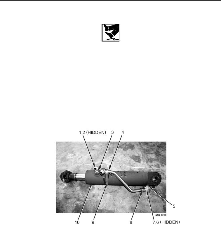
1. Install two new O-rings (Figure 6, Items 2 and 6) and fittings (Figure 6, Items 1 and 7) and tighten nuts
(Figure 6, Items 3 and 5) on clam cylinder (Figure 6, Item 10).
2. Connect tube (Figure 6, Item 8) on fitting (Figure 6, Item 7).
3. Install resilient mount (Figure 6, Item 4) and clamp (Figure 6, Item 9) on clam cylinder (Figure 6, Item 10).
Figure 6. Cylinder.
0271
4. Lightly grease pin (Figure 7, Item 4).
5. Position clam cylinder (Figure 7, Item 1) on bucket assembly and install pin (Figure 7, Item 4).
6. Install new bolt (Figure 7, Item 5), washer (Figure 7, Item 3), and new locknut (Figure 7, Item 2) on pin
(Figure 7, Item 4).