
TM 5-2420-231-23-3
0275
INSTALLATION CONTINUED
NOTE
Install fitting in position noted during removal.
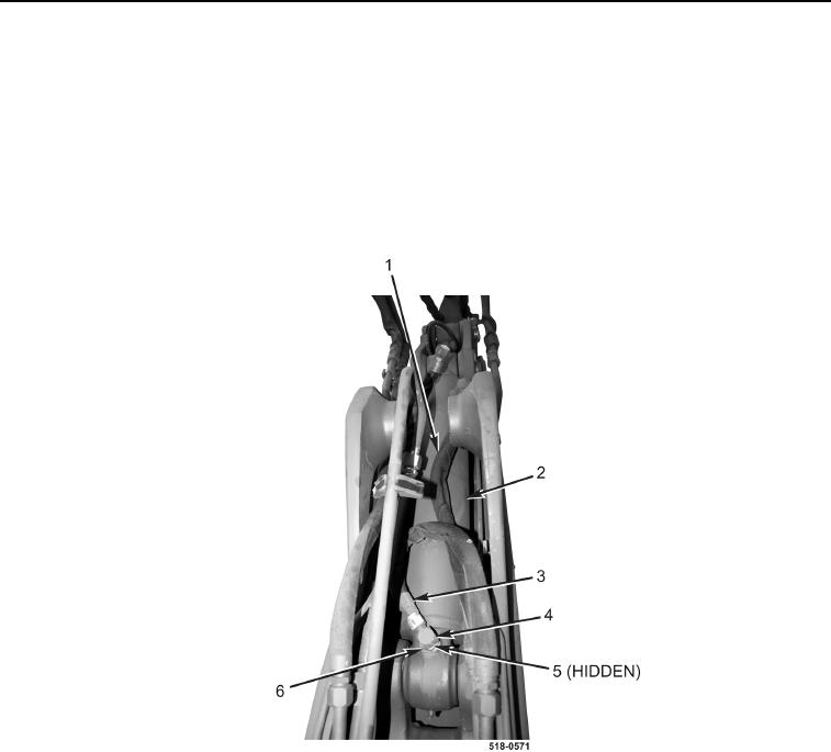
8. Install new O-ring (Figure 8, Item 5) and fitting (Figure 8, Item 4) on backhoe dipper cylinder (Figure 8, Item 2),
and tighten nut (Figure 8, Item 6).
9. Connect hose (Figure 8, Item 3) to backhoe dipper cylinder (Figure 8, Item 2).
10. Connect hose (Figure 8, Item 1) to backhoe dipper cylinder (Figure 8, Item 2).
Figure 8. Dipper Cylinder Hoses.
0275