
TM 5-2420-231-23-3
0276
INSTALLATION
0276
NOTE
Install lines as tagged and marked during removal.
Remove plugs and caps from hoses and fittings.
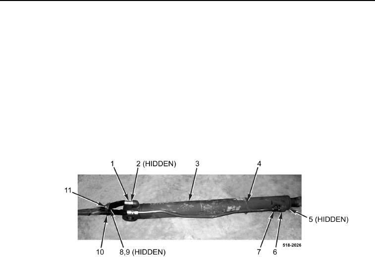
1. Install new O-ring (Figure 5, Item 5) and fitting (Figure 5, Item 6) on backhoe bucket cylinder (Figure 5, Item 3).
2. Connect tube assembly (Figure 5, Item 7) on backhoe bucket cylinder (Figure 5, Item 3).
3. Install new O-ring (Figure 5, Item 2) and connect hose (Figure 5, Item 1) on backhoe bucket cylinder
(Figure 5, Item 3).
4. Install clamp (Figure 5, Item 4) on backhoe bucket cylinder (Figure 5, Item 3).
5. Install two clamps (Figure 5, Item 10), bolt (Figure 5, Item 11), washer (Figure 5, Item 8), and new locknut
(Figure 5, Item 9) on hose (Figure 5, Item 1) and tube assembly (Figure 5, Item 7).
Figure 5. Backhoe Bucket Cylinder.
0276