TM 5-2420-231-23-3
0277
DISASSEMBLY CONTINUED
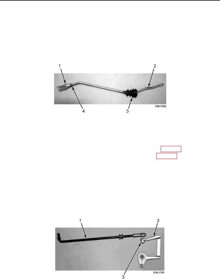
16. Remove bellows (Figure 15, Item 3) from rod (Figure 15, Item 2).
NOTE
Mark clevis and rod for assembly purposes.
17. Loosen jamnut (Figure 15, Item 4) and remove clevis (Figure 15, Item 1) from rod (Figure 15, Item 2).
18. Remove jamnut (Figure 15, Item 4) from rod (Figure 15, Item 2).
Figure 15. Rod, Bellows, and Clevis.
0277
END OF TASK
CLEANING AND INSPECTION
0277
1. Clean and inspect all parts IAW Mechanical General Maintenance Instructions (WP 0369).
2. Clean and inspect all parts IAW Electrical General Maintenance Instructions (WP 0370).
END OF TASK
ASSEMBLY
0277
1. Install jamnut (Figure 15, Item 4) on rod (Figure 15, Item 2).
2. Install clevis (Figure 15, Item 1) on rod (Figure 15, Item 2) and tighten jamnut (Figure 15, Item 4) against clevis.
3. Install bellows (Figure 15, Item 3) on rod (Figure 15, Item 2).
4. Install bellcrank bracket (Figure 16, Item 2) and nut (Figure 16, Item 3) on rod (Figure 16, Item 1).
Figure 16. Bellcrank Bracket and Rod.
0277

