
TM 5-2420-231-23-3
0278
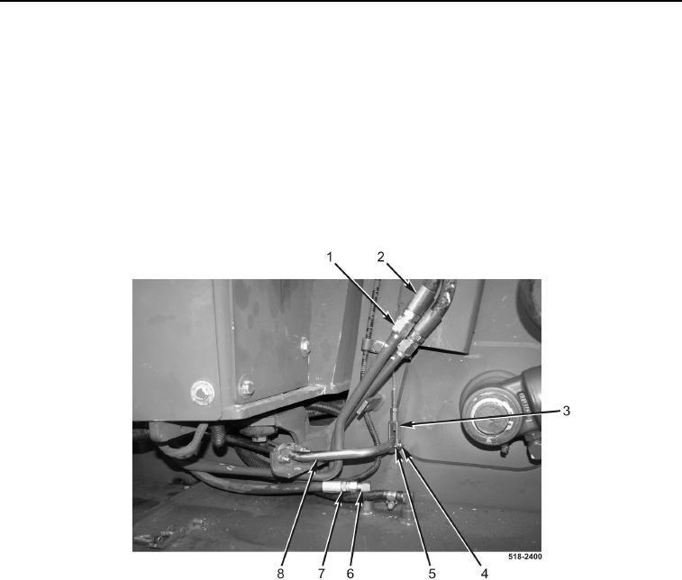
REMOVAL CONTINUED
15. Disconnect hose (Figure 6, Item 7) from fitting (Figure 6, Item 6).
16. Remove cotter pin (Figure 6, Item 5) from pin (Figure 6, Item 4). Discard cotter pin.
17. Remove pin (Figure 6, Item 4) from clevis (Figure 6, Item 3) and rod (Figure 6, Item 8).
NOTE
It will be necessary to rotate loader self-leveler control lever upward in order to remove
tubes from machine.
18. Disconnect two loader bucket tubes (Figure 6, Item 1) from hoses (Figure 6, Item 2), and remove loader bucket
tubes from machine.
Figure 6. Bucket Tubes and Hoses.
0278