
TM 5-2420-231-23-3
0278
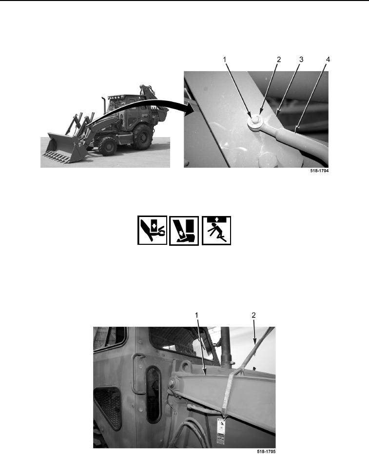
REMOVAL CONTINUED
26. Remove E-clip (Figure 10, Item 1), washer (Figure 10, Item 2), and rod (Figure 10, Item 4) from right-side lift
frame (Figure 10, Item 3).
Figure 10. Lift Frame Rod.
0278
WARNING
Use extreme caution when handling heavy parts. Provide adequate support and use
assistance during procedure. Ensure any lifting device used is in good condition and of
suitable load capacity. Keep clear of heavy parts supported only by lifting device. Failure
to follow this warning may result in injury or death to personnel.
27. Attach sling (Figure 11, Item 2) and lifting device to right side of arm assembly (Figure 11, Item 1) for support.
Figure 11. Support Arm Assembly.
0278