
TM 5-2420-231-23-3
0278
REMOVAL CONTINUED
WARNING
Spring is under tension. Keep fingers clear. Failure to following this warning may result in
injury to personnel.
NOTE
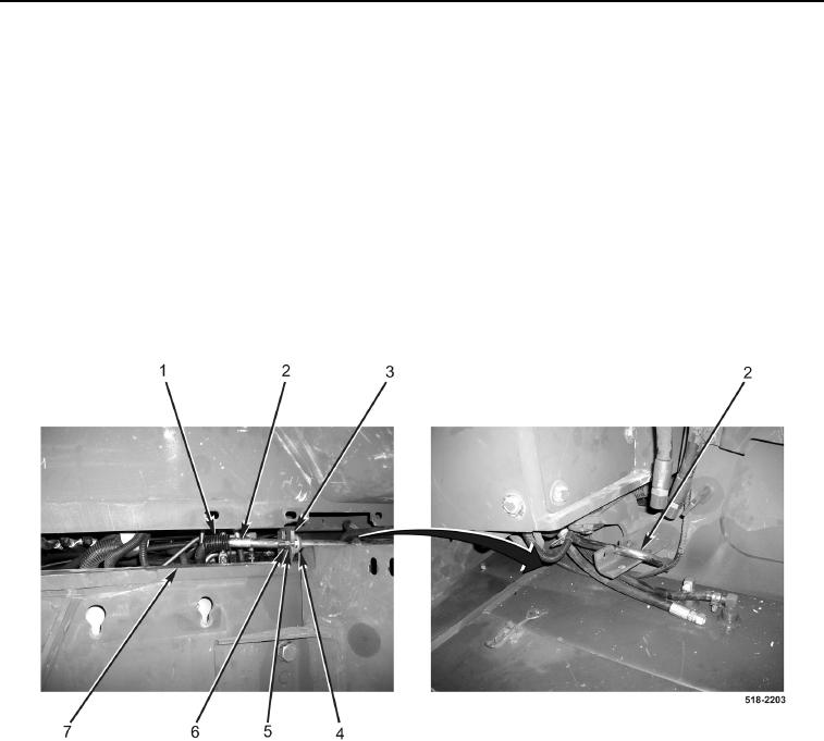
Note how spring is loaded against frame to aid in installation.
23. With assistance, slide rod (Figure 9, Item 2) toward rear of machine.
24. With assistance, disengage spring (Figure 9, Item 1) from machine frame (Figure 9, Item 7).
25. Remove two nuts (Figure 9, Item 6), washers (Figure 9, Item 5), bolts (Figure 9, Item 4), and rod (Figure 9,
Item 2) from bracket (Figure 9, Item 3) and machine.
Figure 9. Rear Rod Bolts.
0278