
30
TM 5-2420-231-23-3
FIELD MAINTENANCE
-
LOADER SELF-LEVELING CONTROLS REPLACEMENT
027
8
Removal, Cleaning and Inspection, Installation, Adjustment
INITIAL SETUP
Tools and Special Tools
Materials/Parts - Continued
Tool Kit, General Mechanic's
Lockwasher (4)
0
0
(WP 0376, Item 117)
Personnel Required
Bar, Cheater (WP 0376, Item 3)
0
Two
Crowbar, Pinch, Heavy Duty, 59"
0
0
(WP 0376, Item 15)
References
Pan, Drain, 5 gal. Capacity (WP 0376, Item 54)
0
0
Pliers, Retaining Ring, Fixed Tip, Convertible,
0
0
45/.090" Tips, 8-3/4" (WP 0376, Item 60)
WP 0374 (Group Number 0704, 0706, 0803,
0
Sledge, Double Face Hammer, 8-lb
and 0804)
0
(WP 0376, Item 78)
Equipment Conditions
Sling, Eye (Nylon, 4 ft x 1 in.)
0
(WP 0376, Item 79)
Loader lowered to ground (TM 5-2420-231-10)
0
Lifting Device (500-lb capacity)
Mud guard removed (WP 0307)
0
0
Front floor plate removed (WP 0306)
Materials/Parts
0
Instrument panel right-side front cover removed
0
Rag, Wiping (WP 0375, Item 25)
0
(WP 0176)
Tag, Marker (WP 0375, Item 33)
0
Estimated Time to Complete
Tiedown Strap (WP 0375, Item 35)
0
9.3 hr
Cotter Pin (3)
0
0
Locknut (3)
0
REMOVAL
0278
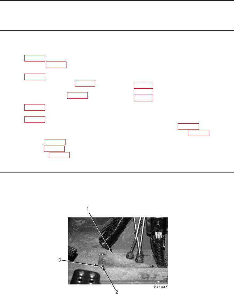
1. Remove four bolts (Figure 1, Item 2), washers (Figure 1, Item 3), and two plates (Figure 1, Item 1) from
machine.
Figure 1. Floor Plate
0278