
TM 5-2420-231-23-3
0278
REMOVAL CONTINUED
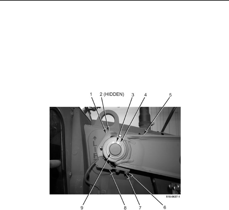
29. Remove two bolts (Figure 13, Item 7), four washers (Figure 13, Item 6), and switch (Figure 13, Item 8) from
arm assembly (Figure 13, Item 5).
30. Remove retaining ring (Figure 13, Item 3) and two washers (Figure 13, Item 4) from right side of machine.
NOTE
Note position of cam and clevis assembly to aid in installation.
31. With assistance, drive pin (Figure 13, Item 9) from right side of machine until clear of arm and clevis assembly
(Figure 13, Item 1) and arm assembly (Figure 13, Item 5).
32. With assistance, remove spring washer (Figure 13, Item 2) and cam and clevis assembly (Figure 13, Item 1)
from machine.
Figure 13. Switch and Cam.
0278