
TM 5-2420-231-23-3
0278
REMOVAL CONTINUED
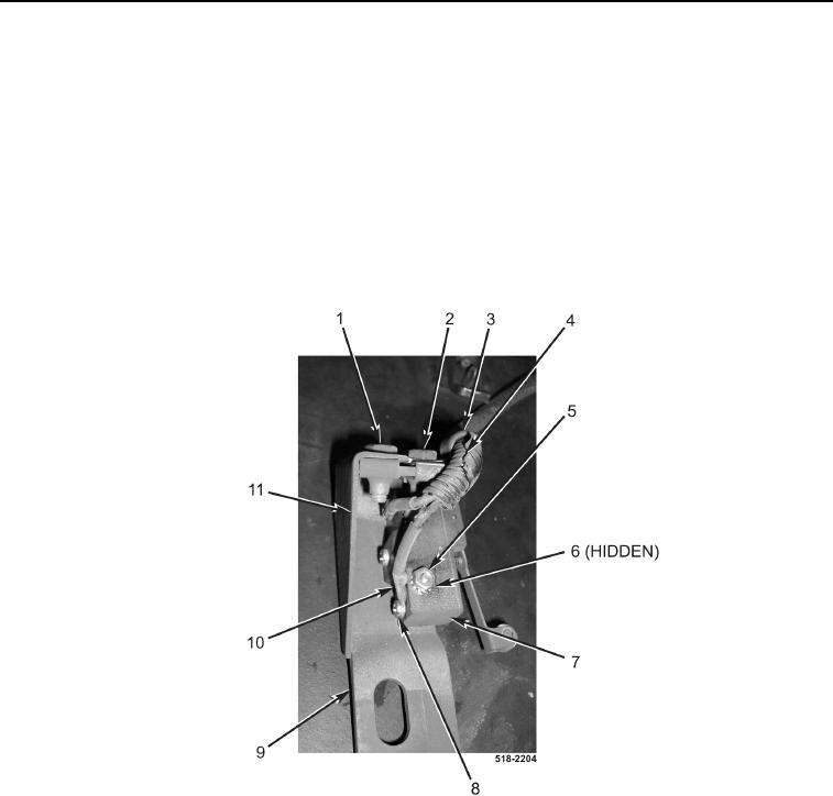
34. Remove bolt (Figure 15, Item 1) and cover (Figure 15, Item 11) from bracket (Figure 15, Item 9).
35. Remove bolt (Figure 15, Item 2) and clamp (Figure 15, Item 3) from wiring harness (Figure 15, Item 4).
36. Remove two locknuts (Figure 15, Item 5), screws (Figure 15, Item 6), and switch (Figure 15, Item 7) from
bracket (Figure 15, Item 9). Discard locknuts.
NOTE
Tag and mark wires to aid in installation.
37. Remove two screws (Figure 15, Item 8) and disconnect two wires (Figure 15, Item 10) from switch
(Figure 15, Item 7).
Figure 15. Switch.
0278