
TM 5-2420-231-23-3
0278
INSTALLATION CONTINUED
WARNING
Hydraulic oil is very slippery. Immediately wipe up any spills. Failure to follow this warning
may result in injury or death to personnel.
NOTE
Remove plugs and caps from hoses and fittings.
Install lines as tagged and marked during removal.
It will be necessary to rotate loader self-leveler control lever upward in order to install
tubes.
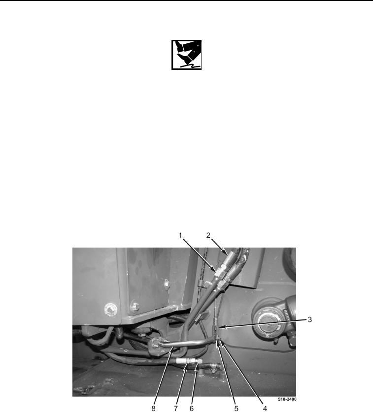
24. With assistance, install two loader bucket tubes (Figure 26, Item 1) on machine, and connect loader bucket
tubes to hoses (Figure 26, Item 2).
25. Install pin (Figure 26, Item 4) on clevis (Figure 26, Item 3) and rod (Figure 26, Item 8).
26. Install new cotter pin (Figure 26, Item 5) on pin (Figure 26, Item 4).
27. Connect hose (Figure 26, Item 7) to fitting (Figure 26, Item 6).
Figure 26. Bucket Lines.
0278