
TM 5-2420-231-23-3
0278
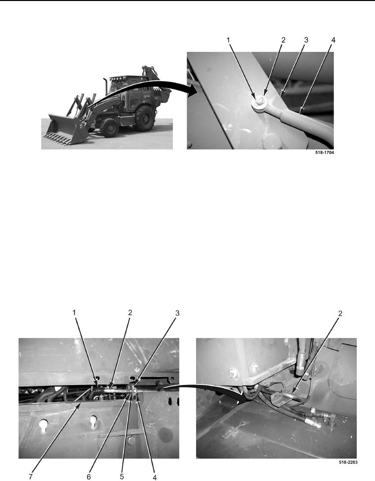
INSTALLATION CONTINUED
Figure 22. Lift Frame Rod.
0278
16. Position rod (Figure 23, Item 2) on bracket (Figure 23, Item 3).
17. Install two bolts (Figure 23, Item 4), washers (Figure 23, Item 5), and nuts (Figure 23, Item 6), on bracket
(Figure 23, Item 3).
WARNING
Spring is under tension. Keep fingers clear. Failure to following this warning may result in
injury to personnel.
NOTE
Load spring against frame as noted in removal.
18. With assistance, engage spring (Figure 23, Item 1) on machine frame (Figure 23, Item 7).
19. With assistance, slide rod (Figure 23, Item 2) toward front of machine.
Figure 23. Rear Rod Bolts.
0278