
TM 5-2420-231-23-3
0278
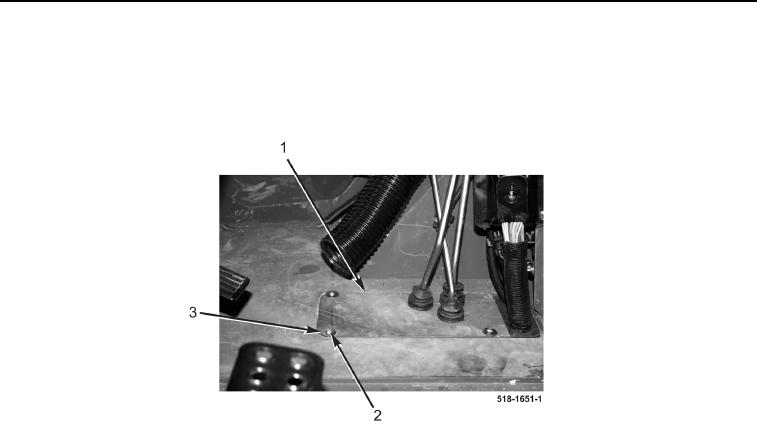
INSTALLATION CONTINUED
38. Install two plates (Figure 30, Item 1), four washers (Figure 30, Item 3), and bolts (Figure 30, Item 2) on
machine.
39. Install cap on hydraulic tank (TM 5-2420-231-10).
Figure 30. Floor Plate.
0278
END OF TASK
ADJUSTMENT
0278
NOTE
Adjust load leveler actuator rod so that it is centered under the front end loader (FEL)
rollback linkage tab at the loader valve.
1. Use washers to shim space between E-clips (Figure 31, Item 4) and bearings (Figure 31, Item 3) moving the
load leveler actuator rod (Figure 31, Item 2) fore and aft as needed.
2. Tighten capscrew (Figure 31, Item 1).