
TM 5-2420-231-23-3
0278
INSTALLATION CONTINUED
NOTE
Install cam and clevis assembly as noted during removal.
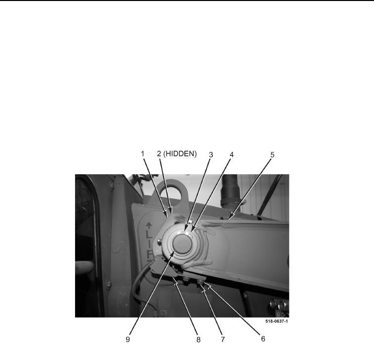
9. With assistance, install cam and clevis assembly (Figure 19, Item 1) and spring washer (Figure 19, Item 2) on
machine.
10. With assistance, drive pin (Figure 19, Item 9) through cam and clevis assembly (Figure 19, Item 1) and arm
assembly (Figure 19, Item 5).
11. Install two washers (Figure 19, Item 4) and retaining rings (Figure 19, Item 3) on machine.
12. Install switch (Figure 19, Item 8), four washers (Figure 19, Item 6), and two bolts (Figure 19, Item 7) on arm
assembly (Figure 19, Item 5).
Figure 19. Switch and Cam.
0278