
TM 5-2420-231-23-3
0278
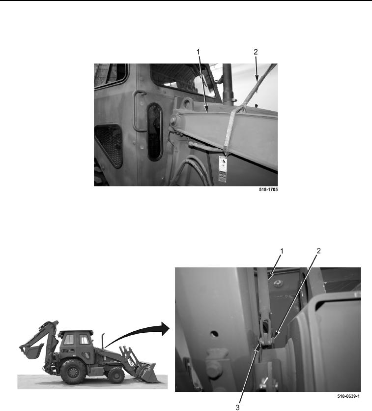
INSTALLATION CONTINUED
13. Remove sling (Figure 20, Item 2) and lifting device from right side of arm assembly (Figure 20, Item 1).
Figure 20. Support Arm Assembly.
0278
14. Position rod (Figure 21, Item 1) on machine and install clevis pin (Figure 21, Item 2) and new cotter pin
(Figure 21, Item 3).
Figure 21. Rod and Clevis.
0278
15. Install rod (Figure 22, Item 4), washer (Figure 22, Item 2), and E-clip (Figure 22, Item 1) on right-side lift frame
(Figure 22, Item 3).