• Home
  • Download PDF
  • Order CD-ROM
  • Order in Print
Figure 8. Lift Frame Installation.
Figure 11. Hoses and Tubes (Right Side).

Tractor, Wheeled, Industrial Backhoe Loader Nsn 2420-01-532-3399
Page Navigation
  441    442    443    444    445  446  447    448    449    450    451  
img
.
TM 5-2420-231-23-3
0279
INSTALLATION CONTINUED
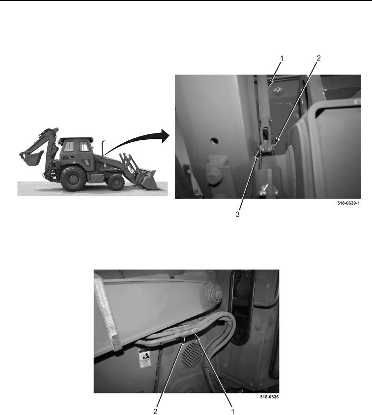
7. Position rod (Figure 9, Item 1) on machine and install clevis pin (Figure 9, Item 2) and new cotter pin
(Figure 9, Item 3).
Figure 9. Rod.
0279
8. Connect four hoses (Figure 10, Item 2) to tubes (Figure 10, Item 1) on left side of loader.
Figure 10. Hoses and Tubes (Left Side).
0279
0279-8


Privacy Statement
Press Release
Contact

© Copyright Integrated Publishing, Inc.. All Rights Reserved.