
TM 5-2420-231-23-3
0279
INSTALLATION CONTINUED
WARNING
Use extreme caution when handling heavy parts. Provide adequate support and use
assistance during procedure. Ensure any lifting device used is in good condition and of
suitable load capacity. Keep clear of heavy parts supported only by lifting device. Failure
to follow this warning may result in injury or death to personnel.
NOTE
Arm assembly weighs 400 lb (182 kg).
Note position and orientation of cam and washer to aid with installation.
2. Attach three slings and lifting device to lift frame.
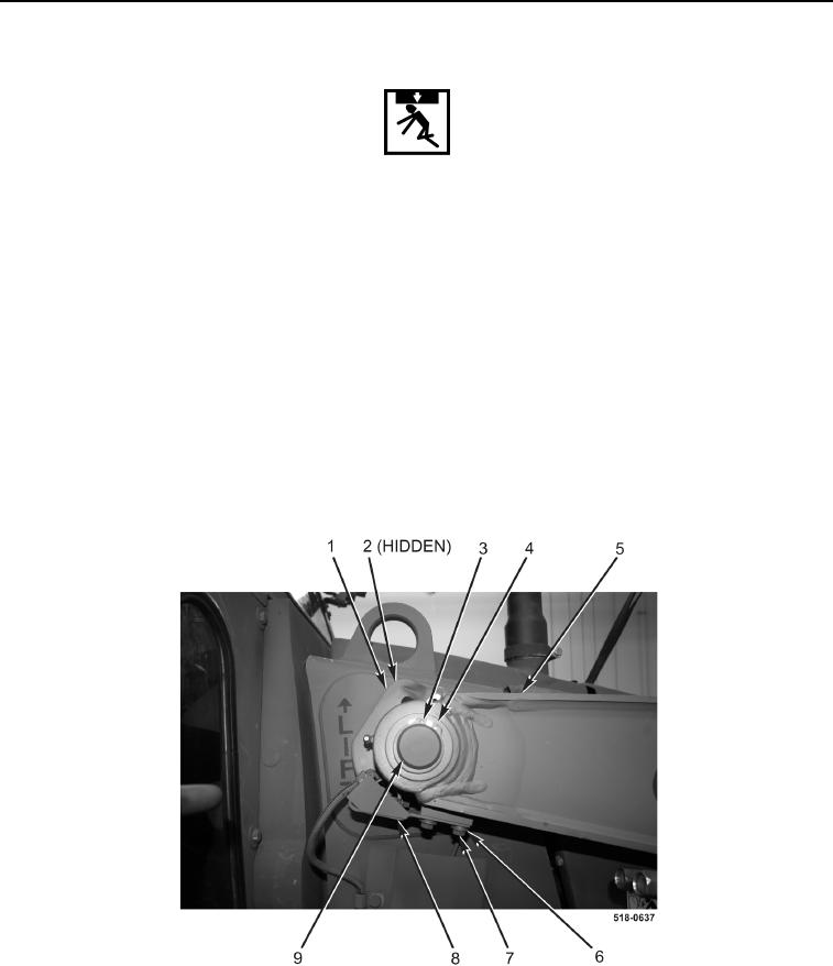
3. Lightly grease pin (Figure 8, Item 9).
4. Using lifting device, install spring washer (Figure 8, Item 2), cam (Figure 8, Item 1), lift frame (Figure 8, Item 5),
and pin (Figure 8, Item 9) on machine.
5. Install two retaining rings (Figure 8, Item 3) and two washers (Figure 8, Item 4) on machine.
6. Install switch (Figure 8, Item 8), four washers (Figure 8, Item 6), and two bolts (Figure 8, Item 7) on lift frame
(Figure 8, Item 5).
Figure 8. Lift Frame Installation.
0279