
TM 5-2420-231-23-3
0286
REMOVAL CONTINUED
NOTE
Note location and quantity of tiedown straps to aid in installation.
Note routing of lines and wires to aid in installation.
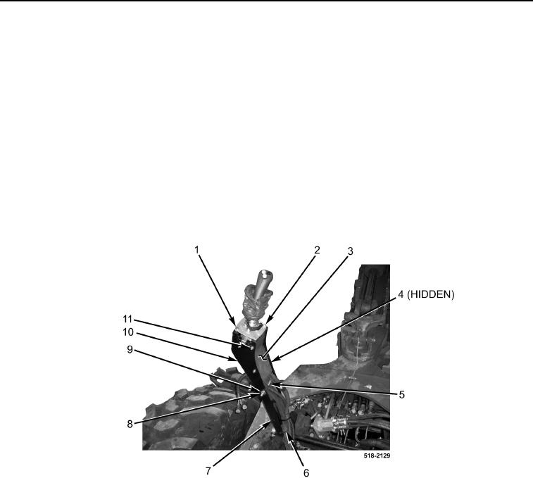
10. Remove tiedown strap (Figure 4, Item 6) from left backhoe control tower (Figure 4, Item 7). Discard tiedown
strap.
11. Remove two bolts (Figure 4, Item 1) from joystick plate (Figure 1, Item 2).
12. Remove four bolts (Figure 4, Item 11) and plate (Figure 4, Item 3) from joystick bracket (Figure 4, Item 10).
13. With assistance, remove locknut (Figure 4, Item 8), two washers (Figure 4, Item 9), spacer (Figure 4, Item 5),
bolt (Figure 4, Item 4), and joystick bracket (Figure 4, Item 10) from left backhoe control tower (Figure 4,
Item 7). Discard locknut.
14. Lay joystick plate (Figure 4, Item 2) aside.
Figure 4. Left Tower.
0286