
TM 5-2420-231-23-3
0286
CLEANING AND INSPECTION
0286
1. Clean and inspect all parts IAW Mechanical General Maintenance Instructions (WP 0369).
2. Clean and inspect all parts IAW Electrical General Maintenance Instructions (WP 0370).
END OF TASK
ASSEMBLY
0286
1. With assistance, position backhoe control tower (Figure 17, Item 8) on backhoe control tower mounting bracket
(Figure 17, Item 4).
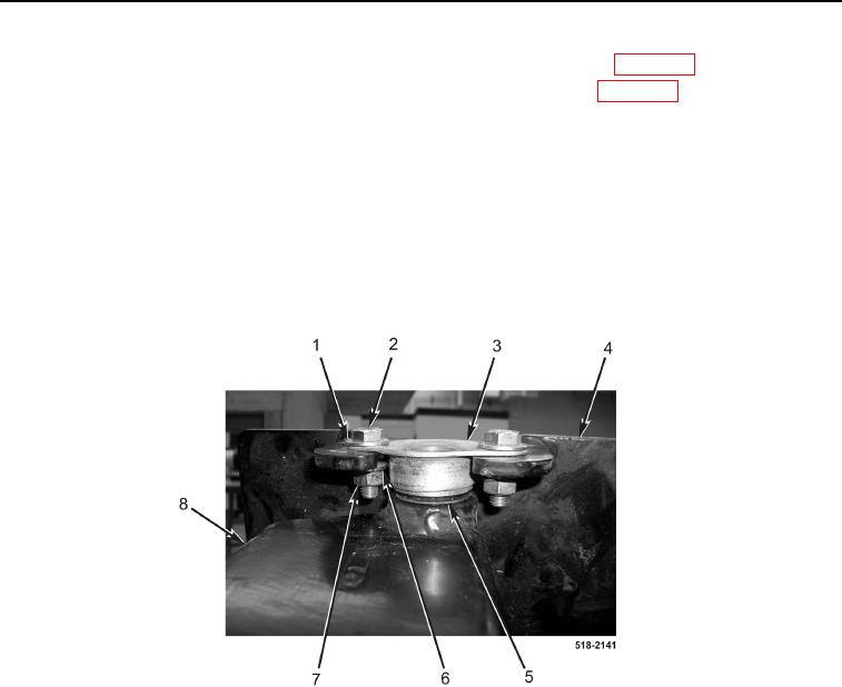
2. With assistance, install two washers (Figure 17, Item 5), bushings (Figure 17, Item 3), eight washers
(Figure 17, Item 1), four bolts (Figure 17, Item 2), new lockwashers (Figure 17, Item 6), and nuts (Figure 17,
Item 7) on backhoe control tower (Figure 17, Item 8).
Figure 17. Backhoe Control Tower Bushings.
0286