
TM 5-2420-231-23-3
0288
INSTALLATION CONTINUED
NOTE
Install jamnuts so cable is at the center of adjustment.
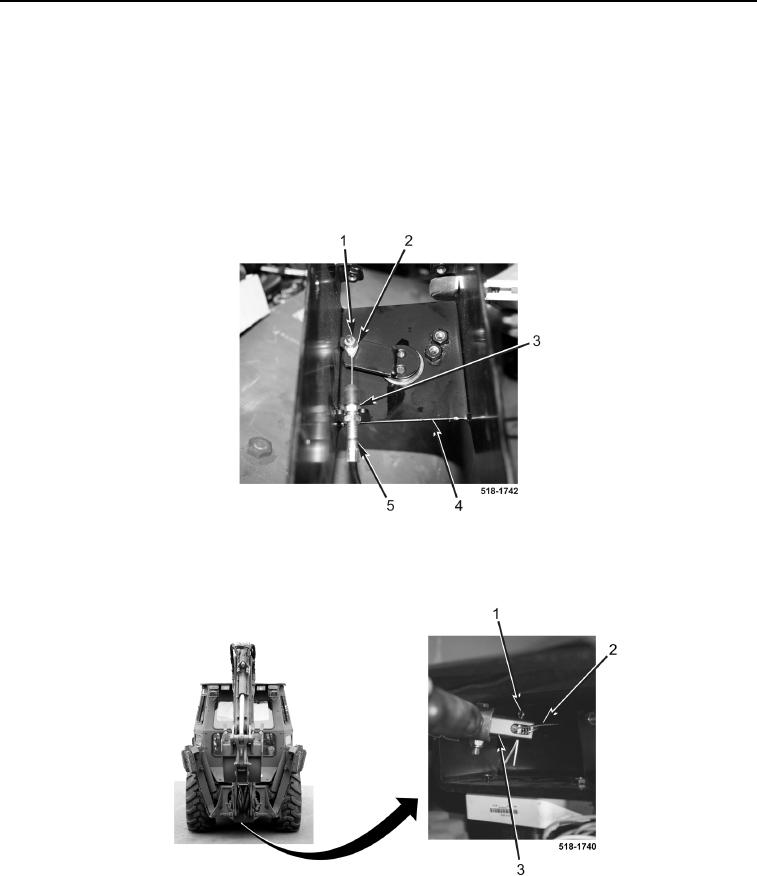
5. Position cable (Figure 8, Item 5) on machine.
6. Install screw (Figure 8, Item 1), cable (Figure 8, Item 5), and new locknut (Figure 8, Item 2) on right-hand joy-
stick bracket (Figure 8, Item 4).
7. Tighten jamnut (Figure 8, Item 3).
Figure 8. Cable.
0288
8. Install cable (Figure 9, Item 2) and new cotter pin (Figure 9, Item 1) on strut assembly (Figure 9, Item 3).
Figure 9. Cotter Pin and Cable.
0288