
TM 5-2420-231-23-3
0288
REMOVAL CONTINUED
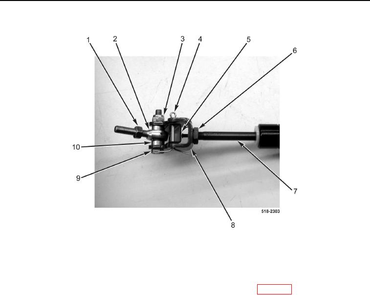
Figure 7. Gas Strut Assembly.
0288
END OF TASK
CLEANING AND INSPECTION
0288
Clean and inspect all parts IAW Mechanical General Maintenance Instructions (WP 0369).
END OF TASK
INSTALLATION
0288
NOTE
Install channel in position and orientation noted during removal.
1. Install bracket (Figure 7, Item 8), channel (Figure 7, Item 5), and new cotter pin (Figure 7, Item 4) on gas strut
(Figure 7, Item 7).
2. Tighten jamnut (Figure 7, Item 6).
3. Install two spacers (Figure 7, Item 10), ball joint (Figure 7, Item 2), new locknut (Figure 7, Item 3), and bolt
(Figure 7, Item 9) on bracket (Figure 7, Item 8).
4. Install jamnut (Figure 7, Item 1) on ball joint (Figure 7, Item 2).