
TM 5-2420-231-23-3
0288
ADJUSTMENT
0288
1. Remove four bolts (Figure 13, Item 5) and cover plate (Figure 13, Item 4) from control tower
(Figure 13, Item 3).
2. Remove two bolts (Figure 13, Item 2) and backhoe control joystick (Figure 13, Item 1) from control tower
(Figure 13, Item 3).
3. Position backhoe control joystick (Figure 13, Item 1) aside.
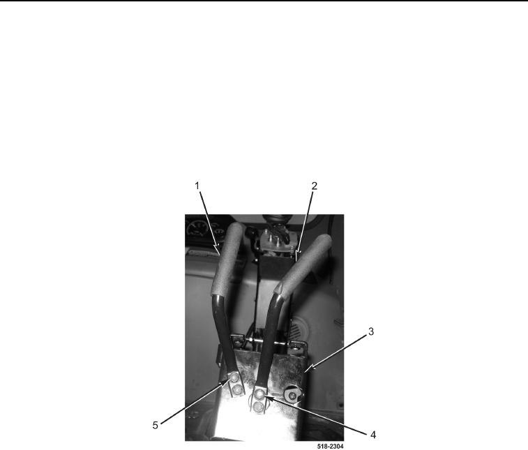
4. Install handle (Figure 14, Item 1) and two bolts (Figure 14, Item 5) on backhoe control tower
(Figure 14, Item 3).
5. Install handle (Figure 14, Item 2) and two bolts (Figure 14, Item 4) on backhoe control tower
(Figure 14, Item 3).
Figure 14. Control Tower Levers.
0288