TM 5-2420-231-23-3
0289
REMOVAL
0289
NOTE
The procedure for stabilizer plate and pad removal and replacement is identical for left-
hand and right-hand stabilizer plate and pad. Left-hand stabilizer plate and pad is shown in
this procedure.
1. Remove two retaining rings (Figure 1, Item 5) and pin (Figure 1, Item 4) from machine.
2. Attach sling and lifting device to stabilizer arm.
NOTE
Note quantity and location of washers to aid in installation.
3. Remove two bolts (Figure 1, Item 6), locknuts (Figure 1, Item 7), pin (Figure 1, Item 3), two washers (Figure 1,
Item 2), and washer (Figure 1, Item 1) from stabilizer pad assembly (Figure 1, Item 8). Discard locknuts.
4. Remove two lockpins (Figure 1, Item 10) and pin (Figure 1, Item 9) from stabilizer pad assembly
(Figure 1, Item 8).
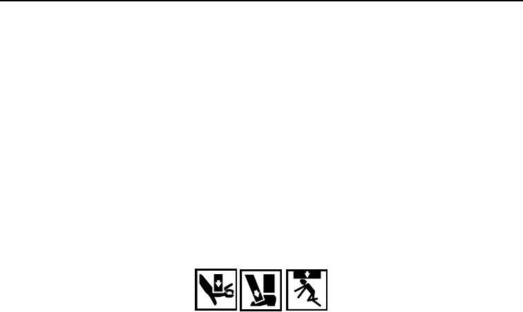
WARNING
Use extreme caution when handling heavy parts. Provide adequate support and use
assistance during procedure. Failure to follow this warning may result in injury or death to
personnel.
NOTE
Stabilizer pad assembly weighs 120 lb (55 kg).
5. With assistance, remove stabilizer pad assembly (Figure 1, Item 8) from machine.
0289-2

