
TM 5-2420-231-23-3
0302
REMOVAL CONTINUED
NOTE
The procedure for pivot bracket and pivot stud removal and replacement is identical for
left-hand and right-hand pivot brackets and pivot studs. Left-hand pivot bracket and pivot
stud are shown in this procedure.
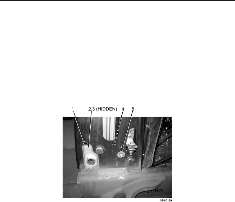
9. Remove pivot stud (Figure 4, Item 5) from cooling pack (Figure 4, Item 4).
NOTE
Mark position of pivot brackets on the cooling pack to aid in installation.
10. Remove two bolts (Figure 4, Item 2), washers (Figure 4, Item 3), and pivot bracket (Figure 4, Item 1) from
cooling pack (Figure 4, Item 4).
11. Repeat steps 9 and 10 for right-hand pivot bracket and pivot stud.
Figure 4. Pivot Bracket.
0302
END OF TASK