
TM 5-2420-231-23-3
0366
INSTALLATION CONTINUED
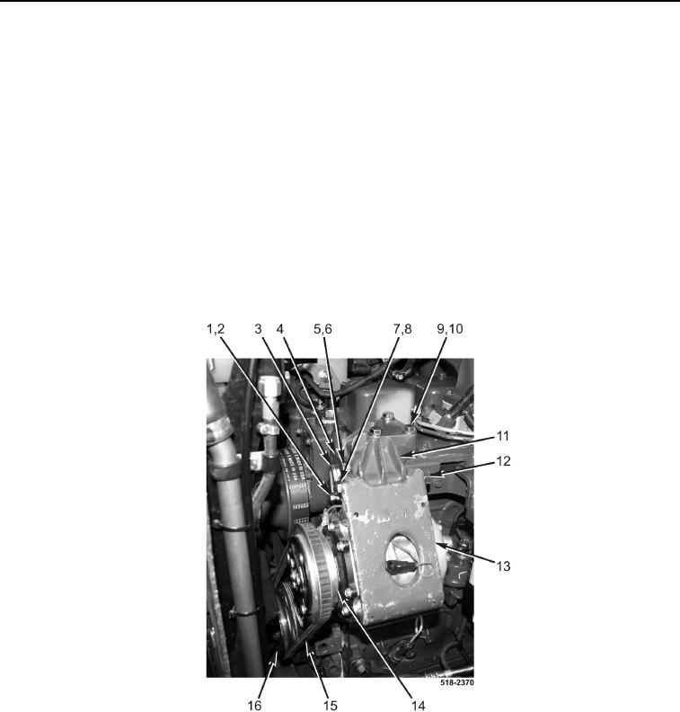
9. Install A/C compressor support mount (Figure 9, Item 11), three washers (Figure 9, Item 10), bolts
(Figure 9, Item 9), washer (Figure 9, Item 6), and bolt (Figure 9, Item 5) on engine (Figure 9, Item 4).
10. Install A/C compressor mounting bracket (Figure 9, Item 13), two washers (Figure 9, Item 8), bolt
(Figure 9, Item 7), and nut (Figure 9, Item 12) on A/C compressor support mount (Figure 9, Item 11). Do not
tighten nut at this time.
11. Install two washers (Figure 9, Item 2) and bolt (Figure 9, Item 1) on A/C adjusting bracket (Figure 9, Item 3)
and engine (Figure 9, Item 4). Do not tighten bolt at this time.
12. Install A/C compressor V-belt (Figure 9, Item 15) on engine pulley (Figure 9, Item 16) and A/C compressor pul-
ley (Figure 9, Item 14).
13. Apply tension to A/C compressor V-belt (Figure 9, Item 15) by pulling A/C compressor mounting bracket
(Figure 9, Item 13) away from engine (Figure 9, Item 4). Tighten bolt (Figure 9, Item 1) on compressor adjust-
ment bracket (Figure 9, Item 3).
14. Tighten nut (Figure 9, Item 12) and bolt (Figure 9, Item 7) on A/C compressor mounting bracket
(Figure 9, Item 13).
Figure 9. A/C Compressor Belt.
0366