
TM 5-3805-255-14
0033
REMOVAL CONTINUED
Foot Throttle -- Continued
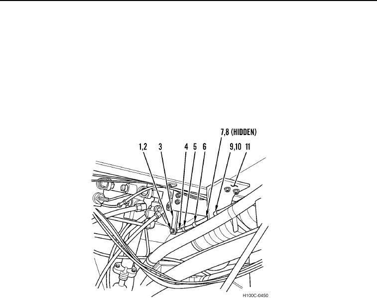
6. Remove nut (Figure 2, Item 1), lockwasher (Figure 2, Item 2), and ball joint (Figure 2, Item 4) from bellcrank
(Figure 2, Item 3). Discard lockwasher.
7. Remove ball joint (Figure 2, Item 4) and top nut (Figure 2, Item 5) from cable (Figure 2, Item 6).
8. Remove nut (Figure 2, Item 7) and lockwasher (Figure 2, Item 8) from cable (Figure 2, Item 6). Discard
lockwasher.
9. Remove cable (Figure 2, Item 6) from bracket (Figure 2, Item 11). Remove nut (Figure 2, Item 9) and
lockwasher (Figure 2, Item 10) from cable. Discard lockwasher.
Figure 2. Foot Throttle (Pedal End).
0033
10. Remove nut (Figure 3, Item 2), lockwasher (Figure 3, Item 3), and ball joint (Figure 3, Item 4) from accelerator
pedal (Figure 3, Item 1). Discard lockwasher.
11. Remove ball joint (Figure 3, Item 4) and top nut (Figure 3, Item 5) from rod (Figure 3, Item 6).
12. Remove nut (Figure 3, Item 2), lockwasher (Figure 3, Item 3), and ball joint (Figure 3, Item 7) from bellcrank
(Figure 3, Item 8). Discard lockwasher.
13. Remove rod (Figure 3, Item 6) from floor board plate.
14. Remove ball joint (Figure 3, Item 7) and bottom nut (Figure 3, Item 5) from rod (Figure 3, Item 6).
15. Remove bolt (Figure 3, Item 9), nut (Figure 3, Item 12), lockwasher (Figure 3, Item 10), and brackets (Figure 3,
Item 11) from bellcrank (Figure 3, Item 8). Discard lockwasher.
0033-2