
TM 5-3805-255-14
0033
INSTALLATION CONTINUED
00033
Foot Throttle
00033
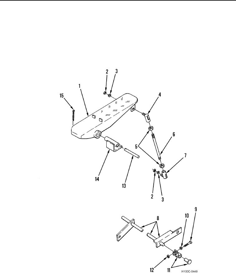
1. Install accelerator pedal (Figure 5, Item 1), pin (Figure 5, Item 13), and new cotter pin (Figure 5, Item 15) on
hinge (Figure 5, Item 14).
2. Install bellcrank (Figure 5, Item 8) on angle brackets.
3. Install two brackets (Figure 5, Item 11), new lockwasher (Figure 5, Item 10), bolts (Figure 5, Item 9), and nuts
(Figure 5, Item 12) on bellcrank (Figure 5, Item 8).
Figure 5. Accelerator Pedal.
0033
0033-6