
TM 5-3805-255-14
0033
INSTALLATION CONTINUED
Foot Throttle -- Continued
4. Install bottom nut (Figure 5, Item 5) and ball joint (Figure 5, Item 7) on rod (Figure 5, Item 6).
5. Install rod (Figure 5, Item 6) through floorboard plate.
NOTE
Be sure end of lever is above arm of bellcrank (refer to Hand Throttle Installation in this
work package).
Bellcrank arm should be horizontal, parallel to floor.
6. Install ball joint (Figure 5, Item 7), new lockwasher (Figure 5, Item 3), and nut (Figure 5, Item 2), on bellcrank
(Figure 5, Item 8).
7. Install lockwasher (Figure 5, Item 10), nut (Figure 5, Item 9) and ball joint (Figure 5, Item 4) on rod (Figure 5,
Item 6).
8. Install ball joint (Figure 5, Item 4), new lockwasher (Figure 5, Item 3), and nut (Figure 5, Item 2) on accelerator
pedal (Figure 5, Item 1).
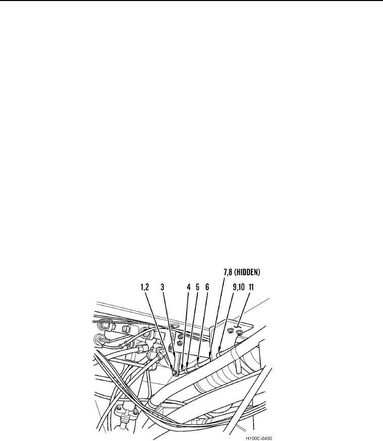
9. Install lockwasher (Figure 6, Item 10), nut (Figure 6, Item 9) on cable (Figure 6, Item 6).
10. Install cable (Figure 6, Item 6) on bracket (Figure 6, Item 11).
11. Install lockwasher (Figure 6, Item 7), nut (Figure 6, Item 8) on cable (Figure 6, Item 6).
12. Install nut (Figure 6, Item 5) and ball joint (Figure 6, Item 4) on cable (Figure 6, Item 6).
13. Install ball joint (Figure 6, Item 4) lockwasher (Figure 6, Item 2), and nut (Figure 6, Item 1) on bellcrank (Figure
6, Item 3).
Figure 6. Foot Throttle (Pedal End).
0033
0033-7