• Home
  • Download PDF
  • Order CD-ROM
  • Order in Print
Figure 2. Gauge Removal.
SENDING UNIT REPLACEMENT

Maintenance Manual For Loader, Scoop Type, Ded 4 X 4, Articulated Frame Steer, 4.5 To 5 Cu. Yd.
Page Navigation
  408    409    410    411    412  413  414    415    416    417    418  
img
TM 5-3805-255-14
0043
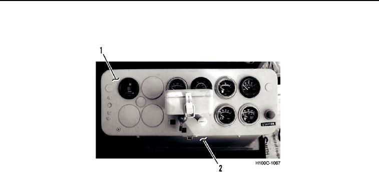
6. Install lamp (Figure 2, Item 2) in gauge (Figure 2, Item 1).
7. Install gauge face plate (Figure 3, Item 1) on instrument panel (Figure 3, Item 2).
Figure 3. Gauge Cluster
0043
8. Turn battery disconnect switch to ON position.
9. Start engine and check operation of gauges.
END OF TASK
END OF WORK PACKAGE
0043-3/(4 blank)


Privacy Statement
Press Release
Contact

© Copyright Integrated Publishing, Inc.. All Rights Reserved.