
TM 5-3805-255-14
0043
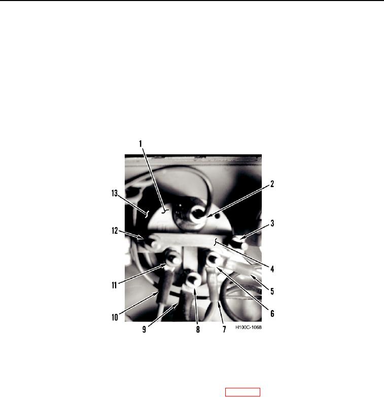
REMOVAL CONTINUED
NOTE
Tag and identify all wires and connectors for aid in assembly.
2. Remove lamp (Figure 2, Item 2) from gauge (Figure 2, Item 1).
3. Remove nut (Figure 2, Item 6) and two wires (Figure 2, Items 5 and 7) from gauge (Figure 2, Item 1).
4. Remove nut (Figure 2, Item 8) and wire (Figure 2, Item 9) from gauge (Figure 2, Item 1).
5. Remove nut (Figure 2, Item 11) and wire (Figure 2, Item 10) from gauge Figure 2, Item 1).
6. Remove two nuts (Figure 2, Items 3 and 12) and bracket (Figure 2, Item 4) from gauge (Figure 2, Item 1).
7. Remove gauge (Figure 2, Item 1) from front of gauge panel (Figure 2, Item 13).
Figure 2. Gauge Removal.
0043
END OF TASK
00043
CLEANING AND INSPECTION
00043
Clean and inspect all parts IAW General Maintenance Instructions (WP 0019).
END OF TASK
INSTALLATION
00043
1. Install gauge (Figure 2, Item 1) in front of gauge panel (Figure 2, Item 13).
2. Install bracket (Figure 2, Item 4) and two nuts (Figure 2, Items 3 and 12) on gauge (Figure 2, Item 1).
3. Install wire (Figure 2, Item 10) and nut (Figure 2, Item 11) on gauge Figure 2, Item 1).
4. Install wire (Figure 2, Item 9) and nut (Figure 2, Item 8) on gauge (Figure 2, Item 1).
5. Install two wires (Figure 2, Items 5 and 7) and nut (Figure 2, Item 6) on gauge (Figure 2, Item 1).
0043-2