
TM 5-3805-255-14
0051
WARNING
Align frame halves and install safety bar with wheels in straight-ahead position. Failure to
install safety bar could lead to serious injury or death.
Ensure wheels are chocked to prevent loader from moving.
REMOVAL
00051
1. Raise vehicle until front wheels are free of floor. Support vehicle using appropriate support stands placed under
main frame.
2. Remove two wheels from axle.
3. Remove propeller shaft from axle (WP 0049).
4. Disconnect two brake lines from axle (WP 0059).
5. Support front axle at each end with a suitable support stand. Position suitable lifting device under differential
bowl of axle.
WARNING
Use extreme caution when lifting heavy parts. Provide adequate support and use
assistance during procedure. Ensure that lifting equipment used is on solid footing, is in
good condition, and is of suitable lift capacity. Keep clear of heavy parts supported only by
lifting equipment. Failure to follow this warning may result in death or injury to personnel or
damage to equipment.
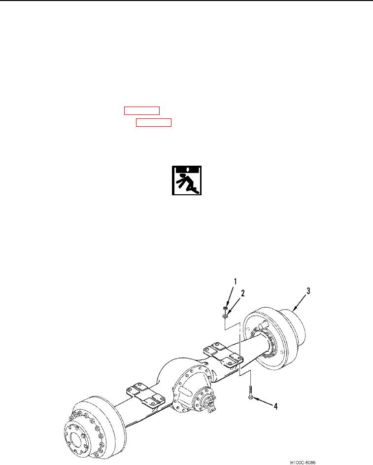
6. Remove eight bolts (Figure 1, Item 4), nuts (Figure 1, Item 1), and sixteen washers (Figure 1, Item 2) from axle
(Figure 1, Item 3).
Figure 1. Front Axle.
0051
0051-2